
What is DMR?
N2CID-DMR-Presentation | Great Video on DMR here!
Digital Mobile Radio (DMR) is an international digital radio standard developed by the European Telecommunications Standards Institute (ETSI), and first ratified in 2005. More than a decade ago, vendors and users of radio systems recognized that the existing analog trunking standards required updates with modern techniques to provide:
- Improved voice quality
- Improved functionality such as Location information)
- Improved security (i.e. Authentication and Encryption)
- Improved channel efficiency (2 slot TDMA)

As a result, today, we have a complete set of standards which cover voice, data services, and conformance testing.
DMR aims to provide an affordable, low-complexity digital standard to replace analog radio. The ETSI DMR Standard defines three different tiers:
- Tier I (unlicensed): DMR equipment works in Direct Mode (unit-to-unit) on public frequencies. Tier 1 DMR devices are best for individuals, recreation, small retail, or other situations that do not require wide area coverage.
- Tier II (licensed conventional): This Tier is aimed to be a direct replacement for the analog conventional radio system. These DMR systems operate under individual licenses working in Direct Mode (unit-to-unit) or using a Base Station (BS) for repeating. It has a degree of wide-area coverage and is targeted at users “who need spectral efficiency, advanced voice features and integrated IP data services in licensed bands for high-power communications.”
- Tier III (licensed trunked): DMR trunking systems operate under individual licenses with a controller function that automatically regulates the communications. It also supports packet data services in a variety of formats, including support for IPv4 and IPv6. It is ideal for organizations looking to migrate from MPT-1327/EADS/LTR (logic trunked radio) systems or who want the full benefits of managed trunking, voice and data solution.
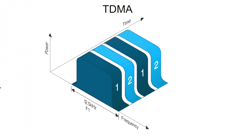
The DMR standard also specifies the use of TDMA technology. TDMA stands for Time Division Multiple Access. TDMA provides two logical channels and each 12.5-kilohertz channel space (see diagram below). This provides a useful doubling of capacity within the same analog channel space.
What is P25?
Project 25 (P25 or APCO-25) is a suite of standards for interoperable digital two-way radio products. P25 was developed by public safety professionals in North America and has gained acceptance for public safety, security, public service, and commercial applications worldwide.[1] P25 radios are a direct replacement for analog UHF (typically FM) radios, but add the ability to transfer data as well as voice, allowing for more natural implementations of encryption and text messaging. P25 radios are commonly implemented by dispatch organizations, such as police, fire, ambulance and emergency rescue service, using vehicle-mounted radios combined with handheld walkie-talkie use.
Starting around 2012, products became available with the newer phase 2 modulation protocol, the older protocol known as P25 became P25 phase 1. P25 phase 2 products use the more advanced AMBE2+ vocoder, which allows audio to pass through a more compressed bitstream and provides two TDMA voice channels in the same RF bandwidth (12.5 kHz), while phase 1 can provide only one voice channel. The two protocols are not compatible. However, P25 Phase 2 infrastructure can provide a “dynamic transcoder” feature that translates between Phase 1 and Phase 2 as needed. In addition to this, phase 2 radios are backwards compatible with phase 1 modulation and analog FM modulation, per the standard. The European Union has created the Terrestrial Trunked Radio (TETRA) and Digital mobile radio (DMR) protocol standards, which fill a similar role to Project 25.
P25 open interfaces
P25’s Suite of Standards specify eight open interfaces between the various components of a land mobile radio system. These interfaces are:
- Common Air Interface (CAI) – standard specifies the type and content of signals transmitted by compliant radios. One radio using CAI should be able to communicate with any other CAI radio, regardless of manufacturer
- Subscriber Data Peripheral Interface – standard specifies the port through which mobiles and portables can connect to laptops or data networks
- Fixed Station Interface – standard specifies a set of mandatory messages supporting digital voice, data, encryption and telephone interconnect necessary for communication between a Fixed Station and P25 RF Subsystem
- Console Subsystem Interface – standard specifies the basic messaging to interface a console subsystem to a P25 RF Subsystem
- Network Management Interface – standard specifies a single network management scheme which will allow all network elements of the RF subsystem to be managed
- Data Network Interface – standard specifies the RF Subsystem’s connections to computers, data networks, or external data sources
- Telephone Interconnect Interface – standard specifies the interface to Public Switched Telephone Network (PSTN) supporting both analog and ISDN telephone interfaces.
- Inter RF Subsystem Interface (ISSI) – standard specifies the interface between RF subsystems which will allow them to be connected into wide area networks
P25 phases
P25-compliant technology has been deployed over two main phases with future phases yet to be finalized.
Phase 1
Phase 1 radio systems operate in 12.5 kHz digital mode using a single user per channel access method. Phase 1 radios use Continuous 4 level FM (C4FM) modulation—a special type of 4FSK modulation[12]—for digital transmissions at 4,800 baud and 2 bits per symbol, yielding 9,600 bits per second total channel throughput. Of this 9,600, 4,400 is voice data generated by the IMBE codec, 2,800 is forward error correction, and 2,400 is signalling and other control functions. Receivers designed for the C4FM standard can also demodulate the “Compatible quadrature phase shift keying” (CQPSK) standard, as the parameters of the CQPSK signal were chosen to yield the same signal deviation at symbol time as C4FM. Phase 1 uses the IMBE voice codec.
These systems involve standardized service and facility specifications, ensuring that any manufacturers’ compliant subscriber radio has access to the services described in such specifications. Abilities include backward compatibility and interoperability with other systems, across system boundaries, and regardless of system infrastructure. In addition, the P25 suite of standards provides an open interface to the radio frequency (RF) subsystem to facilitate interlinking of different vendors’ systems.
Phase 2
To improve spectrum use, P25 Phase 2 was developed for trunking systems using a 2-slot TDMA scheme and is now required for all new trunking systems in the 700 MHz band.[13] Phase 2 uses the AMBE+2 voice codec to reduce the needed bitrate so that one voice channel will only require 6,000 bits per second (including error correction and signalling). Phase 2 is not backwards compatible with Phase 1 (due to the TDMA operation), although multi-mode TDMA radios and systems are capable of operating in Phase 1 mode when required, if enabled. A subscriber radio cannot use TDMA transmission without a synchronization source; therefore direct radio to radio communication resorts to conventional FDMA digital operation. Multi-band subscriber radios can also operate on narrow-band FM as a lowest common denominator between almost any two way radios. This makes analog narrow-band FM the de facto “interoperability” mode for some time.
Originally the implementation of Phase 2 was planned to split the 12.5 kHz channel into two 6.25 kHz slots, or Frequency-Division Multiple Access (FDMA). However it proved more advantageous to use existing 12.5 kHz frequency allocations in Time Division Multiple Access (TDMA) mode for a number of reasons. It allowed subscriber radios to save battery life by only transmitting half the time which also yields the ability for the subscriber radio to listen and respond to system requests between transmissions.
Phase 2 is what is known as 6.25 kHz “bandwidth equivalent” which satisfies an FCC requirement for voice transmissions to occupy less bandwidth. Voice traffic on a Phase 2 system transmits with the full 12.5 kHz per frequency allocation, as a Phase 1 system does, however it does so at a faster data rate of 12 kbit/s allowing two simultaneous voice transmissions. As such subscriber radios also transmit with the full 12.5 kHz, but in an on/off repeating fashion resulting in half the transmission and thus an equivalent of 6.25 kHz per each radio. This is accomplished using the AMBE voice coder that uses half the rate of the Phase 1 IMBE voice coders.[14]
Beyond Phase 2
From 2000 to 2009, the European Telecommunications Standards Institute (ETSI) and TIA were working collaboratively on the Public Safety Partnership Project or Project MESA (Mobility for Emergency and Safety Applications),[15] which sought to define a unified set of requirements for a next-generation aeronautical and terrestrial digital wideband/broadband radio standard that could be used to transmit and receive voice, video, and high-speed data in wide-area, multiple-agency networks deployed by public safety agencies.[citation needed]
The final functional and technical requirements have been released by ETSI[16] and were expected to shape the next phases of American Project 25 and European DMR, dPMR, and TETRA, but no interest from the industry followed, since the requirements could not be met by available commercial off-the-shelf technology, and the project was closed in 2010.[citation needed]
During the United States 2008 wireless spectrum auction, the FCC allocated 20 MHz of the 700 MHz UHF radio band spectrum freed in the digital TV transition to public safety networks. The FCC expects providers to employ LTE for high-speed data and video applications.[17]